Does USFULL VFD has sleep mode?
Yes
Sleep mode introduction
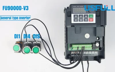
It means that VFD not running when powered on.
How to set up sleep mode?
No need to set it up, when power is on, don’t press any buttons.
What’s the constant pressure control?
Introduction
In industrial occasions, in order to achieve the purpose of energy saving, stable and safe production, it is often necessary to control the pressure of the pipeline through constant pressure. Metering pump is a small constant pressure control system, which has important application value in petroleum, chemical, coal mine and other fields.
Function
- Keep constant water pressure.
- Operate control system manually/automatically.
- Auto switch of multiple pumps.
- Sleep and wake up of the system. When the water use stops, the system is in a sleep status and will automatically wake up when there is a new demand for water.
- Adjust PID parameters online.
- Pump set and line protection detection alarm, signal display, etc.
Application
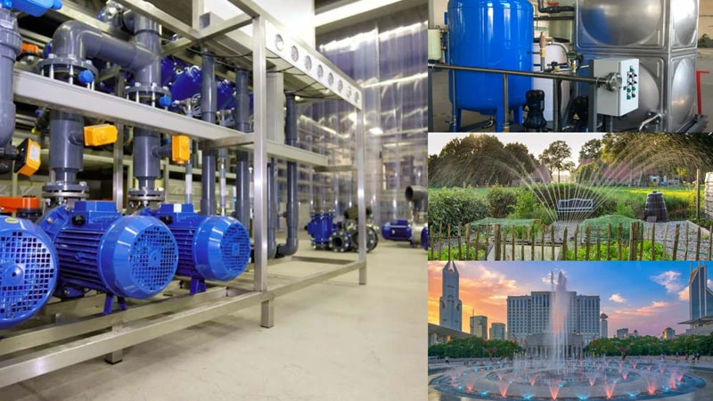
The system can be used for production and domestic water, as well as for hot water supply, constant pressure spray and other systems which constant pressure is required.
- It can be widely used in industrial enterprises, living and production water supply systems and enterprise-owned and renovation projects, water plants, living quarters and fire-fighting water supply systems.
- It can be used for constant pressure, variable pressure, cooling water and circulating water supply systems in various occasions.
- Can be used in sewage pumping stations, sewage treatment and sewage lifting systems.
- It can be used for agricultural irrigation and drainage, garden sprinkler, water feature and music fountain system.
How it works?
During the operation of the equipment, due to the change of load, the pressure of the pipe network changes. The pressure signal is transmitted to the operating inverter through the pressure sensor. After the inverter and the set pressure are compared and calculated, the optimal control signal is generated to control the operation of the pump. Adjust the flow of the pipe network to stabilize the pressure of the pipe network at the set pressure value to meet the system requirements.
The pressure signal from this pipe network is judged and analyzed by the frequency converter: if the system load remains unchanged, the control main pump system is in a dormant state; if the system load is small, the control main pump system is in low frequency operation; if the system load is large, the control main pump system is in a low frequency operation. The pump system is running at high frequency; the system pressure is stabilized at the set value to meet the requirements of the control system.
The constant pressure control system can keep the pressure of the pipe network constant, and can keep the balance between the pipe network and the load, that is, when the load is large, the pipe network flow is large and the pressure is large; when the load is small, the pipe network flow is small and the pressure is small, thereby improving the stability of the system and service quality.
What’s the PID control?
Introduction
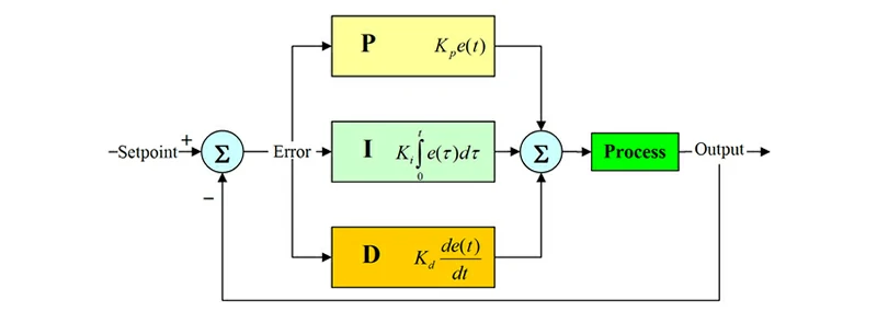
PID control is a kind of control logic that controls the proportion, integral and differential of the error value generated by comparing the collected real-time data information and given target value.
PID control (proportional-integral-derivative controller, or PID controller in short) is a control system with mature technology and the most extensive application.
Control Principle
PID is a classic control algorithm including proportional control (P), integral (I) control and derivative (D) control.
A control loop consists of three parts:
1. The measurement results obtained by the sensors of the system
2. The controller makes a decision
3. React through an output device
The controller gets the measurement from the sensor and subtracts the measurement from the demand to get the error. The error is then used to calculate a correction to the system as an input so that the system can remove the error from its output.
In a PID loop, this correction value has three algorithms, eliminating current errors, averaging past errors, and predicting future errors through changes in error.
Does USFULL inverter have constant pressure control function?
Which model can support constant pressure control function?
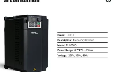
USFULL FU9000D model and FU9000P model.
How to set up constant pressure control function?
FU9000D one pump on inverter constant pressure water supply wiring and parameter setting.
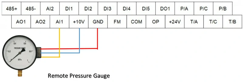
- Remote pressure gauge wiring:
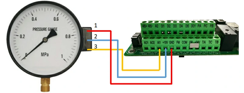
1. Wiring method: 1 to GND, 2 to +10V, 3 to AI1
2. Determine the connection method of the pressure gauge:
Turn the multimeter to Ω, measure the resistance of 1~2, 1~3, and 2~3, find the largest value group, (take 1~2 as an example for largest), then connect 3 to AI1, and then find the smallest value group (take 1~3as an example for smallest), then 1 is connected to GND, and the remaining 2 is connected to +10V.

3. Judge the quality of the pressure gauge:
Turn the multimeter to Ω, measure the resistance of 1~2, 1~3, and 2~3. The largest value group of resistances is about 400Ω, and the other two groups add up to the largest value group, then the pressure gauge is good, otherwise it is broken. If the measured pressure is 0Ω or greater than 400Ω, the pressure gauge is broken.
4. Setting of inverter parameters:
P0-03=8
PA-01=constant pressure value
PA-28=1 sleep parameters
P8-51=sleep frequency
P8-54=wake up stress
Constant pressure value = required pressure / total range of the pressure gauge * 100%,
e.g.: 1.6MPa pressure gauge, the constant pressure is 0.8MPa, then PA-01=0.8/1.6*100%=50.0.
Sleep frequency = the pressure reached and stable is the frequency displayed on the inverter + 2HZ,
e.g.: the pressure reaches 0.8MPa, and the frequency fluctuates with a small amplitude of 30HZ, then P8-51=32.00.
The wake-up pressure is to set the pressure lower than the pressure to restart the pump after sleep,
e.g.: after the sleep reaches 0.8MPa, the pressure is lower than 0.6MPa to start the pump, then P8-54=0.6/0.8*100%=75.
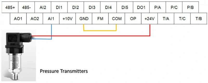
- Pressure Transmitter Wiring
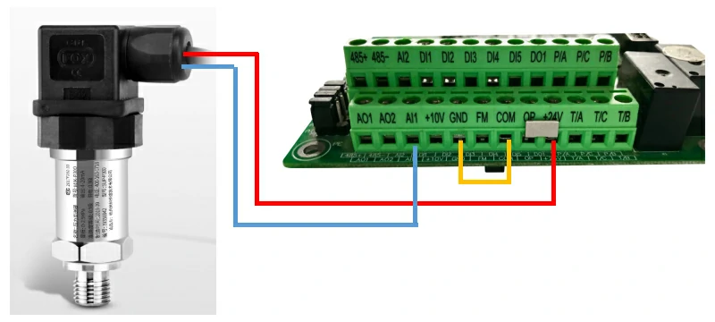
1. The connection method of the two-wire system is as shown above: the red wire is connected to +24V, the blue wire is connected to AI1, and the GND&COM are short connected.
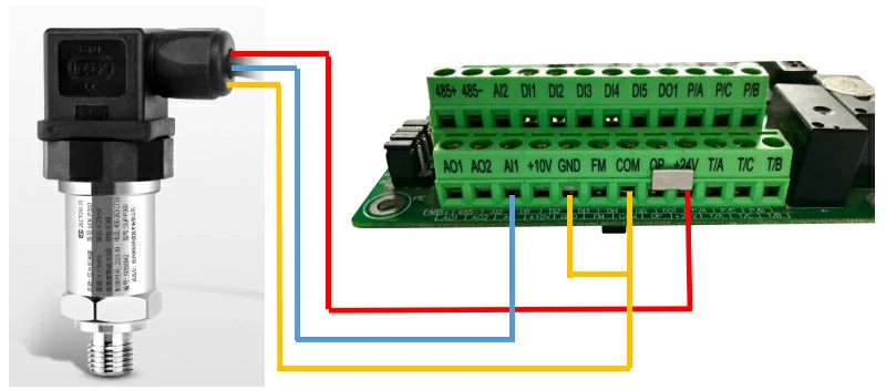
2. The three-wire connection method is as shown in the figure above: the red wire is connected to +24V, the blue wire is connected to AI1, the yellow wire is connected to COM, and the GND&COM are short connected.
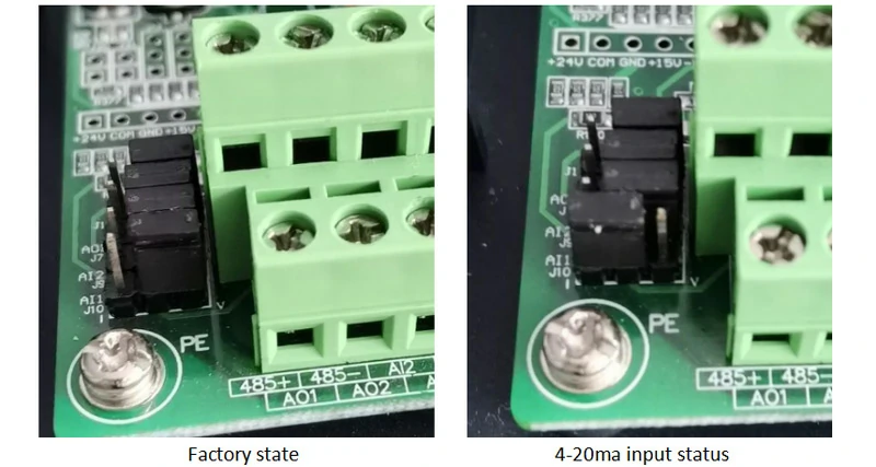
3. The pressure transmitter generally outputs 4-20ma, and the J10 jumper next to the inverter terminal should be changed to current input.
4. Parameter setting
P0-03=8
P4-13=2.00
PA-01=constant pressure value
PA-28=1 sleep parameters
P8-51=sleep frequency
P8-54=wake up stress
Refer to remote pressure gauge for setting method
- What will happen if the pressure gauge is wired incorrectly?
1. When the pressure is reached and the inverter does not stop pumping, the frequency is still running at 50HZ.
Solution: Check the feedback value of U0-16. If it is 0, it means that there is a problem with the wiring of the pressure gauge, or the line is broken and the signal is not fed back to the inverter.
2. There is no response by pressing the RUN inverter.
Solution: Check the feedback value of U0-16. If the maximum value is 1000, it means that there is a problem with the wiring of the pressure gauge.
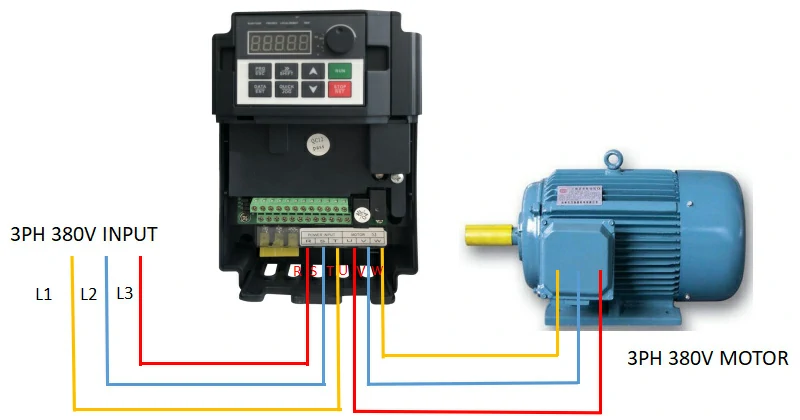
- Overall wiring diagram
